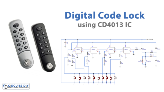
In this tutorial, we are going to make a “Mini tesla coil Circuit”.
In this modern era of wireless technology, we humans are working hard to spread this technology by creating more and more wireless applications. Wireless transmission is useful to power electrical devices where interconnecting wires are inconvenient, hazardous, or not possible. Wireless power transfer technology reduces the use of electric wire which is made of copper and aluminum metal.
The metal which is used to make electric wire will extinct in future that’s why we are moving to tesla coil. A Tesla coil is a radio frequency oscillator that drives the air-core double-tuned resonant transformer to produce high voltages with low currents. This coil can produce output voltages of up to several million volts based on the size of the coil. The Tesla coil works on a principle to achieve a condition called resonance. Here we made a mini tesla coil circuit with a few easily available components, so we can make a CFL bulb glow near the tesla coil without any physical or electrical contact.
Hardware Required
| S.no | Component | Value | Qty |
|---|---|---|---|
| 1 | NPN Transistor | 2N2222A | 1 |
| 2 | Switch | – | 1 |
| 3 | Resistor | 22KΩ | 1 |
| 4 | Inductors 3 turns, 275 turns | – | 1, 1 |
| 5 | LED | – | 1 |
| 6 | Battery | 9V | 1 |
| 7 | Connecting Wire | – | – |
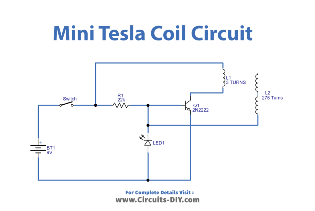
Circuit Diagram
Working Explanation
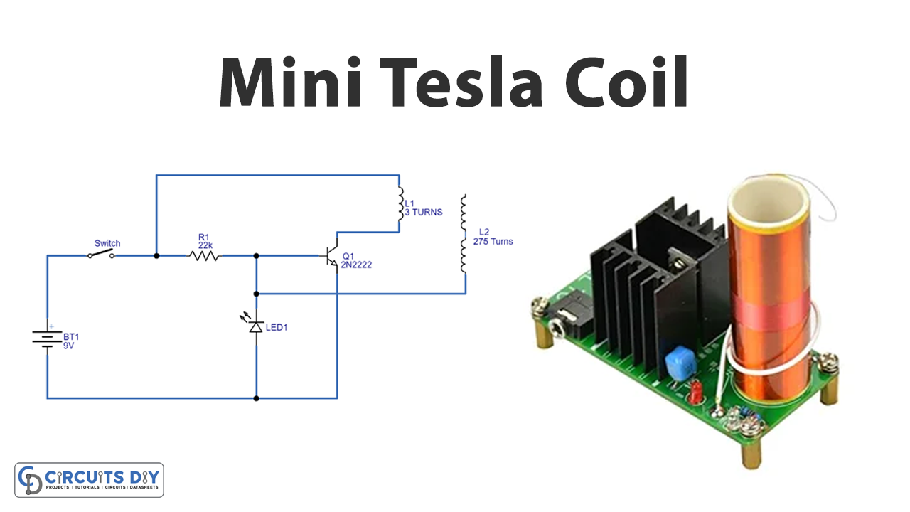
This simple mini tesla coil circuit has two sections, one is a switching section and another one is a step-up winding setup. Single Transistor 2N2222A (NPN) acts as a switching device coil L1 or primary winding is connected at the collector terminal of the Q1 transistor. Hence L1 acts as a magnetic flux-inducing element.
Winding Setup Of Tesla Coil
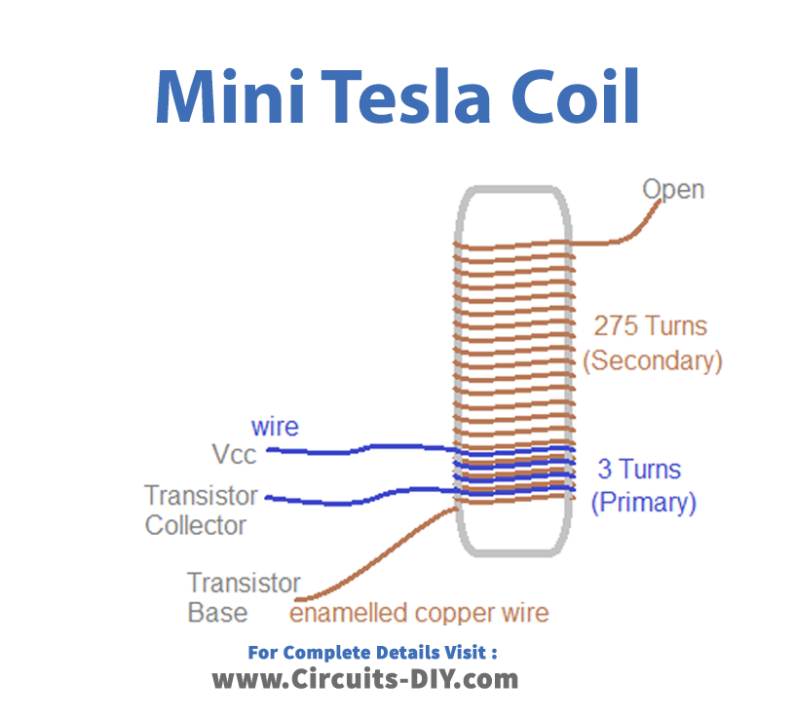
The first important part of the circuit is the tesla coil winding setup. So before proceeding with the circuit, we need to make the winding setup. Here we used 3 inch and half feet PVC pipe (size may vary a little) as non-conducting cylindrical material and a primary coil made with conducting wire. For primary winding make 3 to 6 turns after completing secondary winding, we have used 22 SWG (Standard Wire Gauge) enameled Copper Wire for secondary winding and made 275 turns around PVC pipe. Make sure you follow these tips while winding (Wind the coils as close as possible, do not overlap one coil turn over another, and try to get a minimum of 150 turns, a value of 300 turns will be typically good). One side wire of the secondary coil is connected with the transistor base and another side wire is kept open.
Here battery power supply is connected through the switch to the primary coil and base terminal of the Q1 transistor and placed 22KΩ resistor is at the base terminal. To indicate the oscillating pulse level an LED is connected through the switch between the base and negative supply. The collector terminal of Q1 is connected to the L1 coil, while we connected the emitter terminal to the battery negative supply and the L2 coil is connected to the base terminal.
Now as soon as power applies to the circuit, initially Q1 stays in off condition and coil L1 receives supply due to the threshold level supply flow on the base Q1, which gradually turns ON and completes the power supply flow of the L1 coil. We know that whenever the coil receives the power it will produce magnetic flux and as a result, the magnetic flux near the L2 coil is induced too. Which produces high voltage because it has more turns than the L1 coil. EMF through L2 makes more supply appear at the base terminal, causing transistor Q1 to become active. As a result, the maximum power connected to the battery negative supply through the L1 coil becomes active, causing the power supply through the R1 resistor to the base gets drop, so Q1 becomes a saturated condition. Again, EMF through L2 makes more supply appear at the base terminal, causing Transistor Q1 to become active, and thus the maximum power connected to the battery negative supply through the L1 coil, causing power supply through R1 resistor to base to drop, causing Q1 to become saturated, and so on until there is no power supply to the circuit.
Applications
This coil does not require a complex circuit and so it is part of our daily lives like remote control, smartphones, computers, X-rays, neon and fluorescent lights, and so on.